In addition to delivering a robust step height measurement the ISO 5436 method can also deliver Critical Dimensions such as width and side wall angles. The way the parameters are calculated is controlled from the dialog by defining height values relative to height values found in the step height measurement described in the previous section.
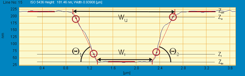
An important element in the width calculation is to determine a linear fit to the sidewalls so that width parameters can be deduced from the crossing points of horizontal lines and the fitted side wall lines. The image shown below illustrates the meaning of the different parameters:
The Lower and Upper Slope Height parameters Zl and Zu, are defined relative to the upper and lower height values found in the step height calculation. The sidewall line is determined by the highest and lowest points inside the z-range given by Zl and Zu, - these points are marked by circles in the above image.
The Lower and Upper Width Height, Zlw and Zuw, defines at which height to measure the width. When drawing horizontal lines at the Zlw and Zuw height values the crossing points with the sidewall lines will determine the upper and lower width, Wu and Wl.
Width and Slope Results
When the structure is successfully detected both the upper Wu and lower width Wl are calculated together with the sidewall slopes measured in degrees. The sidewall angles are indicated as q1 and q2. When more structures are found on the same profile, standard deviation values are calculated such that the uncertainty can be estimated. To obtain a low uncertainty it might be desirable to increase the number of structures and if applicable to include the entire image. Please refer to the previous section for discussion on measurement in an entire image.